
 |
| konfigurasi pin pengawalmikro 8051 |
litar asas mikropengawal ini.


 ni board yang dah siap. Nak cantik lagi kena pandai susun komponen. Letak rapat-rapat. Pakai stripboard pun boleh. Tapi jaga2 soldering jangan sampai short. Masukkan supply 5V pada pin40 dan GND ke pin 20. Pastikan voltan pada reset (pin 9) 0V, bila suis RESET ditekan, voltan akan naik ke 5V. Pin 31 mesti sentiasa 5V. Pada pin 18 dan 19 juga mesti ada voltan yang rendah (1-2V). Kalau takder maknanya sambungan kat pengayun, kapasitor ada masalah. Ataupun pengayun rosak.
Program pakai assembly. ada software yg bg program dalam C. Tp dia akan convert ke hex file gak. Hex file tu kita download ke IC. X kesah bahasa pa kita guna.
Untuk litar sambungan dengan double 7 segment dan aturcar klik sini.
 |
| bc547 |
 |
| relay to bc547 |
 |
| relay to micro controller |
 |
| 2n2222a pinout |
 |
| 2n2222a pinout |
Untuk belajar mengaturcarakan pengawalmikro ni guna assembly language boleh la ke sini.
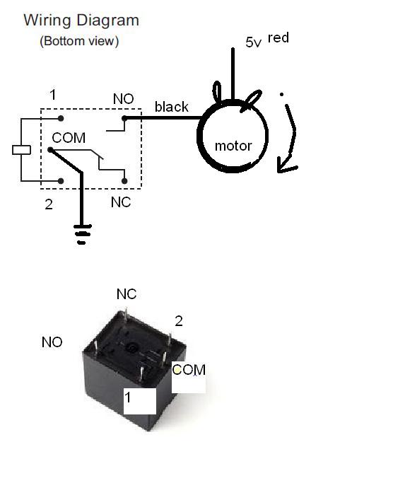 |
| relay pinout connect to motor |
2. LINE FOLLOWER ROBOT USING ATMEL 89S52
 |
| Pandangan Belakang |
 |
| pandangan atas |
 |
| Pandangan sisi |

Konsep yang digunakan pada sensor, kena tambah LED je. R tu ganti ngan petentiometer, perintang bolehlaras.
 |
Litar relay untuk control motor.
|

Litar lengkap yang x guna microc rujuk rajah di atas.

3. RC SERVO MOTOR

Also known as “closed feedback” systems, Servo motors come with a control circuit, which senses if motor mechanism is in desired location and if not it continuously corrects an error until motor reaches the proper point. Servo’s usually come in small plastic packages like the following, but keep in mind there is a whole system inside; motor itself, gears and motor driving and control circuit.
Servo’s usually have great torque because of their gearing. The motor speed decreases, but their torque increases, allowing them to drive high loads. The closed feedback loop mentioned earlier is actually an internal potentiometer that is connected to a mechanical shaft to sense the angle of turn. The signal from the potentiometer provides data to the control circuit to ensure the motor is at the desired angle.
Most servos are designed to operate within a limited range, e.g. 90° or 180°, but can be modified for continuous rotation. This accurate control of rotation and torque thanks to the gearing makes the servo a great device to include in any mechanical-robotic type project. Most servo’s operate from 4.8 to 7.2V DC.
Servo control signals
Servo motor shaft is positioned with pulse width modulated signals (PWM). So all servos comes with three wires (Power, Ground and Control). Usually in hobby servos with rotation angle 90° signal width vary between 1 and 2ms. If pulse is more wide rotation continues until reaches mechanical limits. This signal is applied to the control line of the servo. Refer to your datasheet for more information, but for the example of servos in this tutorial, our servo has a maximum rotation of 180° and operates with a control signal from 1mS to 2mS.
 With this in mind, a signal with a 1.5mS high pulse will tell the servo to go to half way, or a signal at 2mS will make the servo go to 100% deflection. This signal must be sent to the servo once every 1/50th of a second (50Hz), allowing your program to perform many other functions in between. Some servo’s have different pulse requirements for different angles, but most common RC Servos will operate from 1mS to 2mS.
Once a servo is in position, the potentiometer feedback to the servos internal control circuit will ensure that the servo does not drift from the desired position, (providing they are refreshed with the position every 50Hz or 20mS), if there is too much time between the control signals, the servo will drift, and to fast a signal will make the servo chatter. Refer to the datasheet for your servo’s optimal refresh rate.
Also known as “closed feedback” systems, Servo motors come with a control circuit, which senses if motor mechanism is in desired location and if not it continuously corrects an error until motor reaches the proper point. Servo’s usually come in small plastic packages like the following, but keep in mind there is a whole system inside; motor itself, gears and motor driving and control circuit.
Servo’s usually have great torque because of their gearing. The motor speed decreases, but their torque increases, allowing them to drive high loads. The closed feedback loop mentioned earlier is actually an internal potentiometer that is connected to a mechanical shaft to sense the angle of turn. The signal from the potentiometer provides data to the control circuit to ensure the motor is at the desired angle.
Most servos are designed to operate within a limited range, e.g. 90° or 180°, but can be modified for continuous rotation. This accurate control of rotation and torque thanks to the gearing makes the servo a great device to include in any mechanical-robotic type project. Most servo’s operate from 4.8 to 7.2V DC.
Servo control signals
Servo motor shaft is positioned with pulse width modulated signals (PWM). So all servos comes with three wires (Power, Ground and Control). Usually in hobby servos with rotation angle 90° signal width vary between 1 and 2ms. If pulse is more wide rotation continues until reaches mechanical limits. This signal is applied to the control line of the servo. Refer to your datasheet for more information, but for the example of servos in this tutorial, our servo has a maximum rotation of 180° and operates with a control signal from 1mS to 2mS.
Once a servo is in position, the potentiometer feedback to the servos internal control circuit will ensure that the servo does not drift from the desired position, (providing they are refreshed with the position every 50Hz or 20mS), if there is too much time between the control signals, the servo will drift, and to fast a signal will make the servo chatter. Refer to the datasheet for your servo’s optimal refresh rate.
Servo’s have 3 wires, each will be for; +Ve supply, -Ve Supply and Signal.
One thing to keep in mind is that servo’s generate a lot of noise in your circuit. This can lead to very inaccurate timing and strange things happening. To help stop this, be sure to have a large capacitor (around 100uF) near the output of your servo’s +Ve supply, and a 0.1uF Tantalum capacitor as close as possible between the MCU’s +Ve and -Ve pins. Optoisolators are great for isolating circuits from each other, and could be used to great effect with servo’s.
 |
| Circuit Diagram for servo motor |
 |
| servo tester on board |
Sambungan dan Program servo motor menggunakan Atmel 89s51/52
Servo motor ada 3 wayar, samada hitam, merah dan putih atau coklat, merah dan oren. Merah utk 5v, hitam/coklat untk gnd dan putih/oren untuk data pwm dari mikroc.
Sambungan pada port 0.0 pin 39, kalu sambung ke port 2.0 pin 21 kena pasang network resistor sperti di port 0.
Aturcaranya:
ORG 0000H
LJMP BEGIN ;JUMP TO MAIN PROGRAM
BEGIN:
jnb p1.0,left
jnb p1.1,right
jmp begin
left: mov a,#30
left1: setb p2.0 ;suis di port 1.0 utk gerakkan servo ke kiri
setb p0.0
mov r7,#10
call delay5
clr p2.0
clr p0.0
mov r7,#19
call delay
djnz a,left1
jmp begin
right: mov a,#30 ;suis di port 1.1 utk gerakkan servo ke kanan
right1: setb p2.0
setb p0.0
mov r7,#1
call delay5
clr p2.0
clr p0.0
mov r7,#19
call delay
djnz a,right1
JMP BEGIN
;---------------------------------------------
delay: mov r2,#200 ;2 cyc
delay1: nop ;1 cyc
nop ;1 cyc
djnz r2, delay1 ;2 cyc consume 230x4 + 2 instr cycles=922 cyc
djnz r7,delay
ret
delay5: mov r2,#130 ;2 cyc
delay15: nop ;1 cyc
nop ;1 cyc
djnz r2, delay15 ;2 cyc consume 230x4 + 2 instr cycles=922 cyc
djnz r7,delay5
ret
END
selamat mencuba
INFRA RED SENSOR
 |
| Tanpa objek, keluaran pada Vout <1V |
 |
| Ada objek, keluaran naik kepada 2V |
 |
| Litar yg digunakan di atas |
 |
| Yang putih tu transmitter, yg hitam receiver |
Selamat mencuba......
Temperature Sensor


Apabila suhu meningkat, bil LED yg menyala akan bertambah.
 |
| temperature meter circuit diagram |
 |
| LM35 - pengesan suhu |
PIC circuit
My first PIC circuit to blink the LED at portB. Using PIC18F458, program from MPLAB IDE in C language. Download to PIC using LEAPER 48 ROM PROGRAMMER.
 |
| PIC CIRCUIT |
 |
| ROM PROGRAMMER SOFTWARE |
 |
| MPLAB IDE |
 |
| pic board |
 |
| relay board |
 |
| DTMF board |
Projek seterusnya menggunakan arduino uno dan module bluetooth. Software dimuatutrun di google play store.
Connect to bluetooth and press button to light up led or send 1. Send 0 to turn it off.
 |
| Arduino n bluetooth bee 2.0 |
 |
| ANdroid software for bluetooth |
 |
| connect bluetooth |
 |
| light up led by pressing button 1 |
 |
| button 1 pressed |
 |
| file program kawal 2 output pin 12 dan 13 |
Sambungan kepada autogate, buang receiver kepada remote ganti dengan bluetooth dan arduino. ULN2803 juga digunakan bagi membekalkan input ground kepada masukan receiver pada board utama autogate.
 |
| autogate board + uln2803+ arduino uno + blutooth bee |
 |
| bluetooth bee |
 |
| uln2803 |
 |
| autogate |
 |
| Alhamdulillah siap pasang dan berfungsi dgn baik |
 |
| Arduino uno + bluetooth + uln2803 |
Simple Traffic Light Using Arduino
Sila lihat video dibawah. Program juga ditunjukkan dalam video tersebut.
Program arduino dgn ultrasonic sensor dan servo motor.
Mmg mudah programming menggunakan arduino nih. Semua nya ada dlm internet. Search dan terus boleh program. Saya dah cuba untuk ultrasonic sensor dan servo. Program mereka berasingan tp mudah ja untuk digabungkan.
Dalam video ni saya programkan arduino supaya apabila sensor mengesan halangan dlm jarak 5 inci, servo motor akan bergerak (mcm wiper).
Selamat menonton.......
Sesiapa yg berminat pasal arduino ni dan nak selongkar lagi boleh cuba online simulator ni.
 |
| online circuit simulator |
Bkn hanya litar arduino, litar2 lain juga boleh di reka dan di simulasi dalam applikasi ini.
Selamat mencuba.....

salam tuan tanah... :D
BalasPadamsaya ade projek nak gune Microcontroller 8-bit Atmel 89S51/52 nie.. tumpang tanyer kat ner leh dapat...x tau nak beli kat kedai mane
kat butterworth, kg benggali. kt tmpt lain x tau la.
BalasPadamdekat line follower robot tu kalau guna output relay pada sensor tp guna relay tu untuk input kepada microcontroller pakai litar yang sama boleh ke?
BalasPadamboleh hisham....
BalasPadamtq
BalasPadamsetakat 500gram xdak hal la........tp sy blom cuba la. Ada cikgu sekolah buat projek nk angkat wiper dr cermin kreta pun pakai servo motor ni. jd ke x, x tau la, dia x habaq pun.
BalasPadamtgk torque motor(daya kilas @beban yg dia leh bawak) sbb setiap motor ada torque dia sndiri... leh tgk data sheet motor... kalau xda leh test... tp nak test tu cara dia susah skit.
BalasPadamslm.. nk tnya.. kalau kami nk wat projek yg trasfer data dri pc ke mirco c bole gune penyambungan serial port mcm yg atas tu bole ke?
BalasPadamada cara lain. Pakai printer port gak. Sambungan jer lebih sikit. Cuba search kat google, pc interfacing microcontroller.
Padamumm lebih mcm ne ek? saya kurang tau sgt psai interface nie.. ade x litar yg simple je tuk interface pc to micro c nie?
BalasPadamkena search kt google la. boleh pakai printer port atau com port.
Padamsalam....mana boleh dapatkan transistor LM35...
BalasPadamkalau di sini kat butterworth nuu....kg benggali dekat balai polis butterworth nak pergi ke jeti...........
PadamSalam tuan. macam mana kalau kita nak buat alat yang kalau kita cucuk kat soket rokok kat dalam kereta tu dia akan terus baca doa naik kenderaan? Tuan ada idea atau litar dia tak?
BalasPadamTk.
guna fm modulator la. simpan file mp3 bacaan doa tu dalam usb. tansmit ke radio. kena on radio dulu la ikut freq fm modulator tu. boleh simpan doa2 lain dan bacaan alquran sekali. xyah buat beli jer
Padam